The FIX project officially finished in June but I’ve still got some FIX requests hanging around my studio (luckily this was a free service and no-one seems to mind). For 6 months thoughts of these requests have been sitting in the back of my head nagging away; “isn’t it about time you did something about…” – enough already. I decided to use the Christmas break to tackle the most annoying one.
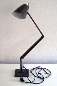
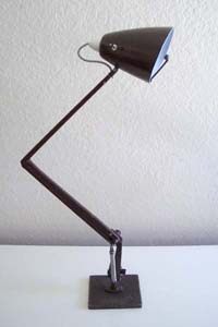
Here it is. A “Planet Lamp” that was listed as an “Ugly Lamp” on the FIX request form.
I decided to turn it into a parabolic microphone.
I think the biggest difficulty I had with this FIX request was that I personally don’t find the lamp ugly, it’s actually one of my favourite designs – I have the floor standing version in my lounge room. The “Planet Lamp” (this one is actually a “Studio K” task lamp) was designed by W.P. (Bill) Iggulden in 1962 for the Australian firm Planet Lighting. The lamp became a design icon and was in production for over 30 years (which is why they are so prevalent in second hand stores around Australia).
This particular lamp was in a fairly typical condition, some small dints, scuff marks, a little loose at the joints, but otherwise working. I considered a number of possible modifications ranging from a simple re-spray to re-casting the entire lamp in flexible silicone rubber. None of my ideas seemed right. After quite a few months I realised I was focusing entirely on the word “Ugly”, I was trying to modify the “Ugly” into the “beautiful” or “interesting” but I couldn’t escape the feeling that in this case ugly = beautiful = interesting. So I decided to shift my attention from the lamps form to its function. If I couldn’t turn the “Ugly Lamp” into a “Beautiful Lamp” I’d make the “Ugly Lamp” an “Ugly …something else”. That “something else” became a parabolic microphone. (why a parabolic microphone? – not really sure, probably something to do with me being a geek and a fan of the 1974 Coppola film The Conversation)
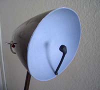
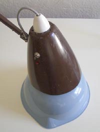
I wanted the modification to have minimal impact on the lamps existing form with all electronic components concealed within the lamp structure. The parabolic reflector is housed in the lamp shade
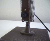
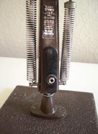
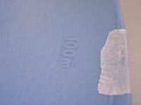
and a headphone socket and volume control was mounted on the lamps base (this image is a close-up of the volume knob).
An extensive internet search uncovered a large number of possible circuit designs for the parabolic microphone. Most of these were based around the operational amplifier chip (Opamp). One of the most popular circuits is a home made headphone amplifier called CMoy. It’s named after the designer Chu Moy who first presented the design in this online article. Versions of the CMoy are littered throughout the internet and they can even be purchased on eBay, assembled inside a mints tin. The CMoy is a very simple, low power amplifier. It’s cheap to build and is designed to run on a 9V battery; making it perfect for my parabolic microphone.
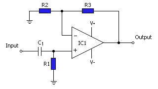
The basic CMoy circuit looks like this. The ratio of resistor 2 (R2) to resistor 3 (R3) sets the amplifier gain; this can be calculated with the formula Gain = (R2 + R3) / R2. IC1 is the Opamp. There are a great number of opamps available; they are used for all sorts of signal amplification and buffering. Douglas Self (a writer for Electronics World magazine and author of the book Self on Audio, Newnes, 2000) has a personal web page devoted to opamps and their audio application. Self’s site is extensive and extremely helpful (and very amusing, while your there check out his Museum of Retro Technology). I decided to use a TL072 opamp. As Self points out, it’s not a particularly good choice for audio amps but it has two distinct advantages; it’s easy to get hold of and it’s cheap. I got mine from Jaycar for AU$2.35. The TL072 has two opamps onboard and although the signal from the mic will be mono I decided to use both the opamps and amp the left and right headphone signals separately. This has the advantage of allowing me to use a stereo headphone jack which will function with both stereo headphones and a mono earphone.
[What am I talking about? Well, generally if you insert a mono plug into a stereo headphone socket then one of the channels, the right channel I think, gets shorted out. This is not generally noticeable because the mono plug will still pick up the left channel. If however the stereo socket is being supplied by a mono signal with left and right channels simply tied together then a mono plug will short out both channels resulting in silence from the earphone. By providing separate amplification for left and right channels a mono plug can be used in the socket and still deliver a signal.]

I used this electret mic insert to provide the signal for the CMoy amp. This is the type of mic insert you’ll find in almost all consumer microphones; they are cheap (about AU$2.50), small (10mm dia.) and sensitive. Tomi Engdahl has a detailed examination of the electret microphone here and a circuit diagram showing you how to hook one up. (He also has a mass of other useful electronic information and links at his website)
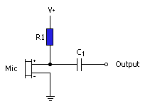
The mic circuit looks like this. As you can see it is very simple; the positive terminal on the electret insert is connected to a +ive supply (generally anything from 1 to 9 volts) through the resister R1, the negative terminal is connected to ground and capacitor C1 is used to block the bias voltage from the audio output. For my mic the +ive supply is 4.5V, R1 is 10K and C1 is 3.3uF.
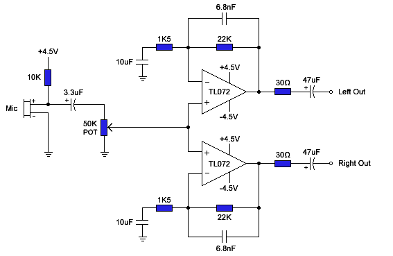
The complete amp. circuit (with both left and right channels) looks like this. The 50K POT controls the output volume and the 6.8nF and 10uF capacitors provide low and high pass audio filters. Signal gain can be calculated as; G = (1.5 + 22) / 1.5 = 15.6 times mic input.
Op-amps generally require a split rail power supply (with balanced positive and negative voltages) and although the TL072 can operate from a single supply rail I had difficulty with this configuration so I opted for the standard split rail supply. A supply voltage of +/- 4.5V was obtained from a 9V battery by using a voltage divider. The power circuit looks like this:
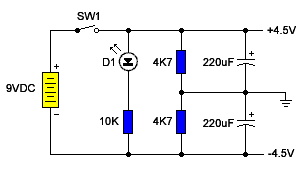
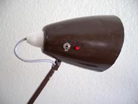
In this circuit the 9V supply is split in half by a pair of 4.7K resistors and a virtual ground is created between the batteries +ive and -ive terminals. SW1 (an ON/OFF toggle switch) and D1 (a red LED) are both mounted on the side of the lamp shade.
As mentioned, the volume control (50K POT) and headphone socket are mounted in the lamps base. The connecting wires follow the same path as the lamps original wiring; exiting the rear of the lamp shade and continuing through the arm of the lamp to the base.
With the lamps original power cord removed, the headphone socket fitted neatly into the vacated hole. The volume control replaces the original ON/OFF switch.
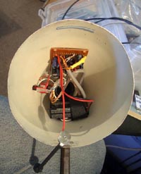
The rest of the electronics, including the 9V battery is fitted inside the lamp shade.
The battery is held in place by a Velcro strap; for easy replacement when needed.
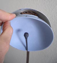
The parabolic dish was a bit of a problem; I searched a number of op-shops for a suitable shaped bowl. Eventually I decided on this plastic mixing bowl.
It’s not a perfect parabola, but it was easy to cut and I love the colour.
I sat the lamp shade on the back of the bowl and traced around the shades front edge. Then I cut the bowl to size with a pair of scissors.
I also sanded the inside of the bowl to remove the internal markings. This gave the dish a soft matt finish. Fixing the dish to the lamp was surprisingly easy. Using the discarded bowl pieces I cut two strips of plastic, one was glued inside the front edge of the lamp shade, the other to the back of the dish. When the dish is pushed into place these plastic strips interlock and stop the dish from moving.
In front of the dish you can see the electret mic. It’s positioned at the dishes focal point at the end of a brass tube. The whole mic assembly is covered in black shrink wrap.
So, does it work? …well, yes and no. It does amplify the sound and it’s slightly directional but it suffers from the small size of the parabolic dish; it’s not really in the same league as the gadgets from The Conversation. A larger parabolic collector would definitely increase it’s effectiveness; but despite these short comings I think it turned out pretty well.
Thanks to Anna for submitting the lamp to FIX, I’ll be returning it to you shortly.

17 Comments