** Amendment: Before you embark on this journey (or maybe you’re just spectating?) I should let you know that, thanks to an industrious modder, you can now buy an adapter to connect a desktop drive to a laptop IDE connector. Check out this forum for details. **
I’m using a laptop for my MP3 computer mod, but I want to use a large, cheap desktop hard drive with it. This became strangely complicated. Although there seems to be an adaptor for every other connection you could possibly want to make in computer land, there doesn’t seem to be a simple solution for this. You can get an adaptor for connecting a laptop HD to a desktop IDE bus but not for connecting a desktop HD to a laptop IDE bus. I decided to make my own.
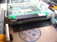
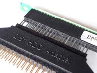
The HD connector for my Powerbook G3 (Wallstreet) looks like this. It’s a fairly common situation were the laptops 2 1/2″ HD plugs directly into the connector. I needed to convert this to the larger 3 1/2″ style connector. I couldn’t find a male 2 1/2″ connector to plug into the existing socket so I decided to modify an adapter that’s designed to attach a laptop HD to a desktop IDE bus – these are quite common, I got mine for about AU$5.
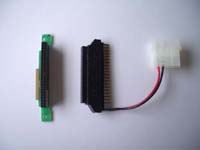
The laptop HD adapter is also designed to plug directly into a laptop HD, so it too has a female 2 1/2″ style connector. In order to join these two female connectors together I needed a double row of header pins.
I couldn’t find header pins at the correct spacing so I cut 1 cm lengths of wire and inserted them into the holes on the female connector (this picture shows me inserting the wire into the Powerbook connector, however after doing this a couple of times I found it was actually easier if the wire was first inserted into the laptop HD adapter).
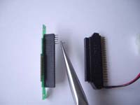
Joining two female connectors together in this way causes a problem; the pins end up transposed either horizontally (pin 1 on connector A ends up connected to pin 43 on connector B) or vertically (pin 1 on connector A ends up connected to pin 2 on connector B). This can best be understood by holding the two connectors on top of each other, in the same orientation and then folding the top connector over so that the two connectors are facing each other. In this movement you can see that the top row of holes on the top connector end up facing the bottom row of holes on the bottom connector (pin 1 ends up facing pin 2). This problem however can be overcome if we flip the pins back again at the other end of the adapter (which we will do latter).
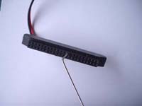
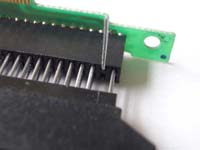
Both the powerbook connector and the laptop HD adapter are keyed to prevent the laptop HD being attached incorrectly. You can just make out the key (the blocked hole) at the end of the metal pointer in the above photo. This is pin 20 on the connector. These two keys need to be aligned, however because of the problem of the flipping pins (outlined above) the keys will end up on opposite rows (pin 20 on the laptop HD adapter will end up facing pin 19 on the Powerbook connector). This prevents a connection being made to pin 19, but luckily this pin is designated a ground connection and in all the hard drives I tested (both laptop and desktop) pin 19 was internally connected to the other ground pins (pins 22, 24, 26), so leaving pin 19 unconnected should not be a problem.
The missing wires at pins 19 and 20 can be seen above. Also missing are wires at pins 41 and 42. This is because the laptop HD adapter I had does not make use of these pins. The +5V power signal for the adapter is on pin 44. The Powerbook connector however (and all standard 44 way Mini IDE hard drives) has the +5V signal on pins 41 and 42; pin 44 is marked as reserved. The laptop HD adapter gets away with having the power on pin 44 because most laptop drives tie pin 44 to pins 41 and 42. The Powerbook connector doesn’t do this (pin 44 is not connected), so if I want to get +5V from the connector I’ll have to tap into pin 41 or 42.
I inserted a piece of wire into pin 42 of the Powerbook connector and bent the wire off to the side.
I then pushed the two connectors together. The wire from pin 42 can be seen sticking out the side of the connector assembly. The Powerbook HD connector has now been converted to a row of standard IDE header pins, but we SHOULD NOT connect an IDE cable directly to these pins, doing so may destroy you drive, your laptop or both. As discussed earlier, plugging a female socket onto this header would flip the pin connections to the opposite row (pin 1 would be at pin 2, pin 3 at pin 4, etc.). We need to turn the male header pins into a female IDE socket. I did this by soldering a female connector to the pins.
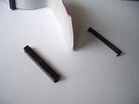
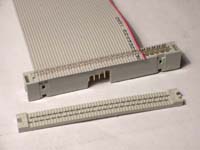
I removed the female connector from a standard IDE ribbon cable (I’ll reuse the rest of the cable latter on). This can be done by pushing out the clips that hold the front and back of the connector together, and then removing the ribbon cable from the connector.
I then twisted each of the metal ribbon connectors so they made contact with the header pins on the adapter (this can be seen in the above picture).
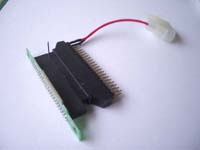
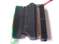
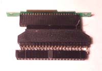
I soldered the female connector in place (the solder looks worse in the photos :-). Note: the plastic tab on the female connector (this is the lump you can see in the centre of the female connector) should be on the same side as the powerbook strip connector (the tag that plugs into the Powerbooks motherboard). I also disconnected the power connector from the adapter. (These pins, along with the pin 42 wire will be used latter in the MP3 mod.)
The adapter is now (kind of) finished, you could plug it directly into a standard IDE hard drive, but this is a little cramped and I decided it was better to attach the drive via a cable. I thought I’d just go out and buy an IDE extension cable (IDE male to IDE female) but, as with everything else, I couldn’t find one. That’s ok, I’ll make my own, but I also couldn’t find any in-line male IDE connectors. I decided to use an in-line male SCSI connector I pulled off an internal SCSI cable.
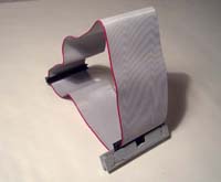
I cut the raggedy end of the IDE ribbon cable I’d butchered earlier and fitted the SCSI connector. SCSI connectors have more pins than IDE connectors, you can cut them down in size if you want, I didn’t bother. You will need to enlarge the key in the SCSI connectors plastic to allow for the tab on the female IDE connector.
The SCSI connector should be orientated on the ribbon cable so that the cables own IDE connectors can plug into the SCSI socket without twisting the cable (i.e. you should be able to make a loop with the cable, like the one above).
With the cable completed, it’s time to try out the adapter.
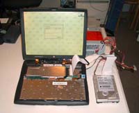
Here you can see the adapter connecting a 3 1/2″ drive to the Powerbook. The drive is powered by an external supply. You should connect the power supply ground to the Powerbooks ground circuit to avoid a voltage differential. I made the ground connection between a black ground connector on the power supply and pin 43 on the adapter (note: for me pin 43 was the pin that originally had the red wire attached NOT the black wire – this is due to the flipping of the pins I discussed earlier).
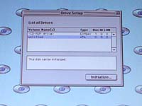
And voila, it works. The hard drive shows up as ATA, Bus 0, ID 0.
This was a cheap but rather complicated construction, there may be an easier approach but I haven’t found one, if you have let me know.
One last thing; as with everything on my site, this is not a recommendation, just documentation. If you choose to follow in my footsteps, you do so at your own risk. It worked for me but things can go wrong, don’t do this to something you can’t live without.
Happy Modding.
21 Comments