I’ve had this post sitting in draft mode for 6 months. In that time there’s been a seasonal shift in Melbourne; it snowed last night at my brother’s house in Mt Egerton. The air is crispy fresh and today my mood seems to be getting in line – time to blow away some cobwebs.
Back in Dec. 2007 . . .
It’s stinking hot in Melbourne at the moment, forcing me and my white underbelly into our caverness 1940’s suburban house. This forced retreat shouldn’t really bother me, I’m no stranger to indoor activity – my success as Yarrawonga junior carpet bowls champion ’87 is a testament to that, but for some reason it has me pacing the chocolate swirl carpet and peeking through cracks in the venetians.
I should be putting this time to good use; I’m way behind on my thesis and I have a design project that has managed to become a lifetime commitment. These things need attention, but instead I find myself blogging (I think this is the real secret behind the popularity of blogs, they are an amazing tool for procrastination).
The topic of today’s post; the iPod Mash.
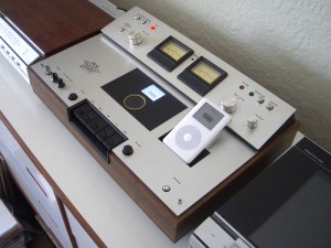
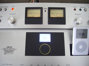
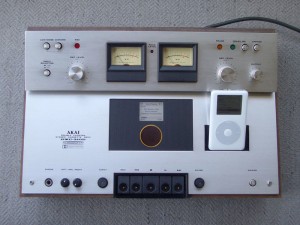
With my previous post I left the iPod Super project hanging, but things haven’t really been as dormant as this absence would suggest. In fact if you check out my entry in this [ed. last] years Mac Mod Challenge you will see that the project has come to a partial conclusion in the form of the iPod Mash (shown above). The iPod Mash combines a 4th generation iPod, a 3.5” hard drive, and a 1975 AKAI tape deck to produce an MP3 mixing console. Tape transport controls are modified to operate an internally mounted iPod, level meters show internal and AUX/dock inputs, and volume knobs adjust the audio mix.
As a dedicated reader (hello friend) you’ll know this story began with Rory’s broken iPod. That little fella (the iPod not Rory) has lead me on quite a journey: iPodLinux, iSOP, iPod Super, but I think this will be it’s final resting place. For a brief overview of the iPod Mash project you should visit the Mac Mod Challenge page, for the excruciatingly detailed specifics, read on.
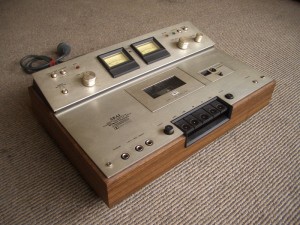
In late 2007 I found an AKAI GXC-310D stereo cassette deck amongst Fitzroy North’s hard rubbish.
The basic premiss for this mod was to provide a case with a suitable interface for an iPod Super. Aside from this requirement the units functional outcome was determined by the physical attributes of the AKAI deck. The fact that the deck mirrored many of its controls across the left and right channels suggested the incorporation of two music sources. I decided the main music source would be an internally mounted iPod with 3.5″ hard drive (an iPod Super).
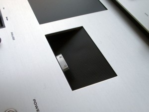
The small cut-out panel to the right of the AKAI’s tape compartment (originally housing the tape counter) was the perfect dimensions for an iPod docking station, this serves as the second music source.
Existing volume knobs and level meters were used as the control interface for the two sources. By incorporating a stereo mixing circuit into the unit, each channel can be independently controlled before being routed to the line-out connectors at the rear.
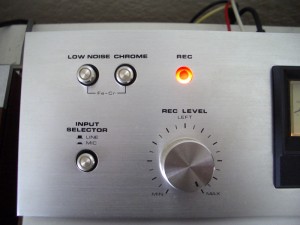
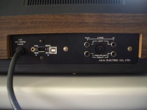
Most of the other controls quickly fell into place. Existing line-in connectors at the rear of the unit prompted the inclusion of an auxiliary music source (for an external CD player or similar). The existing ‘INPUT SELECTOR’ switch was assigned the task of switching between these line-in sockets and the iPod dock.
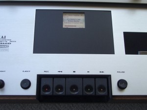
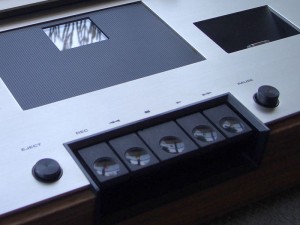
The AKAI’s five tape transport keys mapped easily onto the iPod’s five button click wheel. Working from left to right the key functions are menu, rewind, select (click wheel centre button), play and fast forward. The select button becomes the AKAI’s stop key. This key is larger than the others and is centrally located, making the new interface quite intuitive to use.
Through this re-tasking of the original user interface the ‘scripted use’ of the AKAI tape deck, conveyed through the units material specificity, is shifted into a new registrar. The ‘script’ is taken beyond the realm of ‘prescribed use’ and transposed into a domain of ‘other’ uses. The act of modding becomes a ‘scripted re-use’, a form of ‘play’ where the modder engages the objects script as a set of rules to be negotiated and manipulated. It is through this ‘play’ of creativity and constraint that modding gains the power to shift our perception of objects, to make them function under another logic, and to open up new vistas within material culture. The iPod Mash combines the scripts of the iPod and AKAI tape deck to discover a new formulation that is neither wholly alien nor entirely familiar.
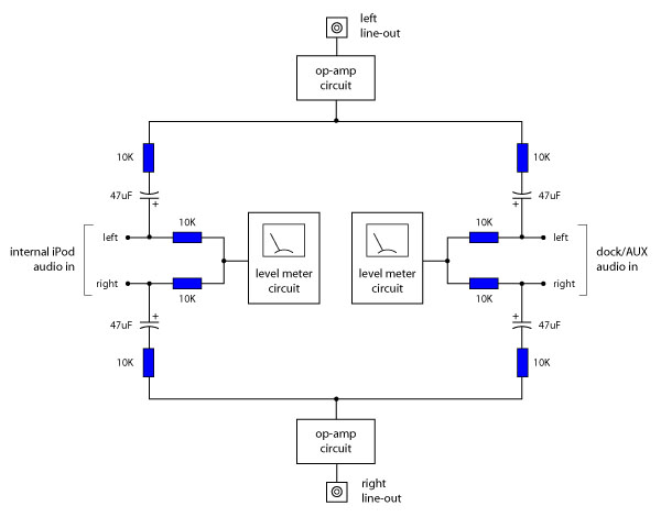
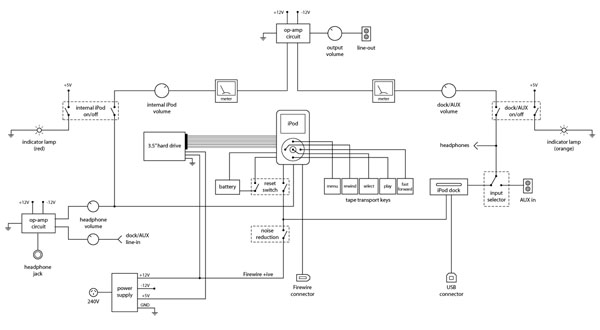
The various components of the iPod Mash are outlined in the following diagram.
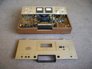
The AKAI GCX-310D, built in the mid 70’s, has a material abundance that you’re unlikely to find in the mass produced products of today – the top surface is solid 3 mm aluminium plate.
Initially, I was hoping to reuse some of the tape player’s internal circuits such as power supply, level meter circuits, and amplification. This however proved to be beyond my technical ability and in the end I decided to gut the unit and start with a clean slate. Existing knobs, buttons, switches, power cord, meters, and in/out sockets were reused, as was the shielded audio hook-up wire inside the unit. All other components for the mixing deck were sourced elsewhere.
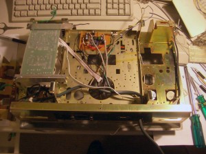
The units pressed metal internal structure is integral to the decks construction; top and bottom panels mount to this structure sandwiching the wooden surround between them. Once the mechanical components, motors and circuit boards were stripped away this structure provided ample opportunities for mounting the new circuits and 3.5″ drive.
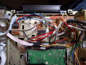
The power supply originated from a printer (possibly from an Apple Stylewriter or Imagewriter, but it’s been sitting in a box for so long I can’t be certain). It was a perfect fit for the unit, both physically and electronically, providing +ive and -ive 12V for the opamp circuits and +12V, +5V for the 3.5″ hard drive (the power supply is located to the left of the following image).
I’m not sure of the power supplies wattage but I did discover it had difficulty powering the hard drive when all 5 of the units original 12V indicator lamps were lit. After replacing these globes with high brightness white LEDs this was no longer a problem; and it made the existing colour bezels really stand out.
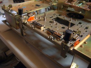
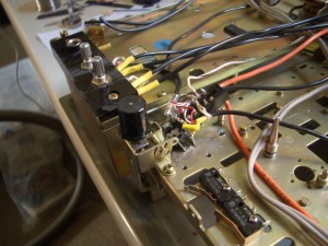
I installed a row of micro-switches behind the tape transport piano style keys providing normally open, single throw switches equivalent to the bubble switches found on the click wheel.
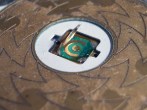
The bubble switch is an extremely simple device, a small metal dome sits on a ring contact with a second contact pad located centrally under the dome.
The dome is held in place by a thin plastic skin. When pressed the metal dome deforms and contacts the central pad, bridging it to the outer ring. When soldering to bubble switches there is generally no need to dissect the bubble itself. The standard bubble switch has a square footprint with electrical contacts at each corner. The contacts on one side of the switch are connected to the internal pad while the remaining two contacts on the other side connect to the outer ring. In the absence of a multi-meter you can simply solder to any diagonally opposite corners to bypass the bubble switch.
Wires from each of the five click-wheel buttons were routed (via a ribbon cable) to the micro switches.
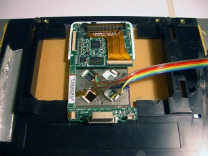
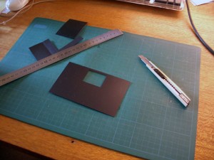
The plastic face of the click-wheel was removed; with a little bit of effort this peels straight off (but don’t use a metal tool to pry it free, you could damage the underlying surface). The click-wheel functions fine without the plastic front but I placed it behind a thin sheet of black plastic (similar to the plastic used for the cover of cheap sketch books).
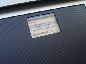
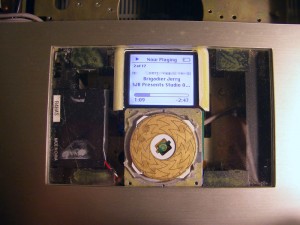
The iPod’s ribbon cables are a bugger to work with, they tear easily and are near impossible to extend. I decided to leave both the click-wheel and screen cables intact. This limited my mounting options and the final layout mirrors the standard iPod with the scroll wheel located centrally just below the screen. Luckily this arrangement fitted neatly into the AKAI’s tape compartment.
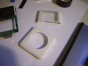
I cut the iPod’s plastic front panel in half and re-used the top section to mount the iPod screen and circuit board; the click-wheel was installed flush with the acrylic sheet.
The round buttons to the left and right of the tape transport keys are used to activate the main and AUX/dock audio sources. These buttons operate independently of each other allowing both sources to play simultaneously (and hence be mixed/mashed together).
There are two opamp circuits, one for the line out and another for the headphone out. These separate amplifiers allow for tracks to be queued through the headphones without interrupting the main output. Headphone volume is controlled by two knobs (one for each music source) located next to the headphone jack (they’re installed in holes originally used for dual mic jacks).
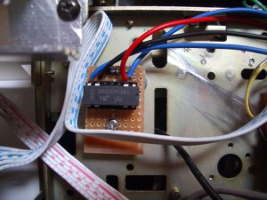
The two amplifier circuits are basically identical. I used the ultra low noise NE5534AN opamp, mainly because my local electronics store (Jaycar) had them in stock. At $3.95 a chip (I needed 4) it’s an expensive opamp, but I was very impressed with the quality. In fact I think this is the cleanest opamp circuit I’ve ever made.
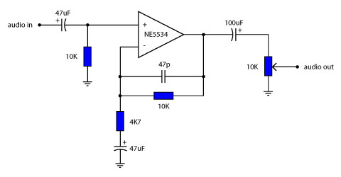
The circuit is based on Douglas Self’s excellent notes on opamp design. All resistors are metal film 1/2 watt; volume pots are 10K dual gang logarithmic. A single decoupling capacitor of 100nF was installed between the +ive and -ive supply rails close to the NE5534 opamps. Douglas Self recommends the cap be installed within a few inches of the NE5534 in order to prevent internal oscillation. Multiple decoupling caps are not necessary and may introduce noise into the circuit.
The level meter circuit was adapted from Andy Collinson’s audio schematics. My circuit is almost identical to Andy’s however I changed the discharge capacitor to 10uF to give faster meter readings (and I substituted some resistor values – they just happened to be what I had lying around).
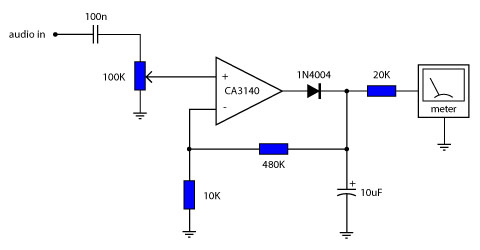
The opamp and level meter circuits are incorporated into a mixing circuit based on schematics from all-electric.com and Tomi Engdahl.
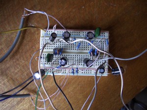
All circuits were trailed on bread boards,
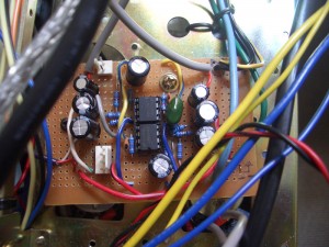
before being transferred to pre-punched experimenters board.
Internal audio connections were made with shielded hook-up wire. Shielding was connected to ground at one end only to minimise ground loops.
A 5V SPST DIL reed relay was installed between the internal iPod and it’s battery. This relay is used to cut power to the internal iPod when the unit’s main power is switched off.
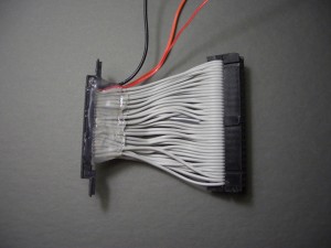
The iPod 3.5″ hard drive connecting cable came from my previous iPod Super experiments. I kept this cable as short as possible in order to avoid interference (both audio and digital).
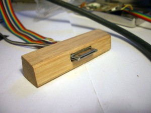
iPod dock connectors were used to connect to the internal iPod and to construct the built-in dock.
These connectors were purchased through the Ridax website. This site developed out of demand from members of the iPodLinux forum. It uses the ‘group buy’ logic to provide iPod connectors to hobbyists.
Pin out details for the iPod dock connector can be found on the iPodLinux wiki site (and also here). I connected the internal iPod to Firewire and the built-in dock to USB – connection ports were installed in the unit’s rear panel.
Initially I had trouble getting the Firewire connection to work, however after swapping the data lines around everything now seems to function correctly. This is a bit odd because my pin outs seem to differ from those detailed on the iPodLinux site; I may be confused but just in case I’m not here are my ‘working’ connections.
PIN WORKING iPodLinux
22 TPB- TPA-
24 TPB+ TPA+
26 TPA- TPB-
28 TPA+ TPB+
Although modern iPods do not have a Firewire interface they can generally be charged through the Firewire pin on the dock connector. I decided to connect Firewire power to the built-in dock; this was less complex then rigging USB power (which requires a sensing resistor). This generally works ok, however I sometimes notice ground hum developing when the USB connection is in use. To remedy this I installed a ‘noise reduction’ switch which can be used to disconnect the Firewire power when necessary.
I decided not to relabel any of the AKAI’s controls – I like their retro look. Initially this can be a little confusing but with some playing around the various functions soon become clear.
The finished interface opperates as follows,
from left to right on the upper panel:
- group of two push switches choose which audio channel (AUX or dock) is active in the headphone
- light (red) indicates if internal iPod source is active
- single switch selects between AUX line-in and iPod dock
- left volume knob controls the internal iPod volume
- meters give level reading for internal iPod (left) and dock/AUX (right)
- light (orange) indicates if dock/AUX source is active
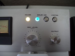
- light (blue) indicates if noise reduction is active
- push switch turns on noise reduction
- far right push switch activates system reset (cuts power to internal iPod)
- right volume knob controls the dock/AUX volume
- far right volume knob controls the main output level
and on the lower panel:
- iPod screen with touch scroll wheel
- iPod dock
- headphone jack
- two headphone volume knobs, one for the internal iPod, one for the dock/AUX
- left circular button activates the internal iPod source
- tape transport keys act as iPod buttons: menu, rewind, select, play/pause, and fast forward
- right circular button activates the dock/AUX source
- far right main power button
This post brings the project to a close. The iPod Mash is now back with Rory; it functions as his lounge room music source and has been running for many months without fault. Overall, a successful project and nowhere near as complicated as my B&O MP3 Mod. I may make one or two more of these…
3 Comments